TASMOTA WITH ESP

WHAT IS TASMOTA

HOW WE CAN USE WITH ESP    DEVICES


Tasmota is a open source custom firmware that can run any devices those have ESP chips.If you want to do some projects for your Smart Home in very easy way . Then you can use TASMOTA platform .No need to know much of  any code here . So it is for you if you do not  know more of coding . 


OK-LET US MAKE A SIMPLE PROJECT WITH ESP01 (ESP8266),DHT-11 AND LED .


Needed Parts -

1-ESP-01

2-DHT-11

3-LED

4-Bread board 

5-Arduino uno or ESP01 programming Adopter (For Flashing)

          (We can program ESP-01 with Arduino or ESP-01 programming Adopter)


            FLASHING WITH             ARDUINO UNO

Connections-

1-Vcc to 3.3 volt

2-GND to GND

3-CH-PD to 3.3 volts

4- RX to RX

5-TX to TX

6-GPO0 to GND

7-GPO2 to Not connected

8-RST - will connect only uploading time for a while.


Note- Arduino RST and GND will be short .Because need to bypass Arduino and program will direct upload on ESP-01 Connect the Arduino with PC with Data cable.Now we can flash (program) ESP01 .


      FLASHING WITH ESP-01 ADAPTER                               


Adopter with Esp-01


Procedure -Fix the ESP01 on Adapter .push the Flash button and Insert the adapter in PC.


Release the Flash button Now and flash the program on ESP 01 .


 Please  fallow the procedure as given below steps .

Step-1   Download Tasmota firmware from given link,
                    http://ota.tasmota.com/tasmota/release/.
                 
You can get more Firmware ,Please download Tasmota bin file.


Step-2  - Download Flashing Firmware from given link 
                    latest Tasmota version 


Note-
You can find here both system for Win-32 and for Win 64 .So what ever you need for your PC download and install it.

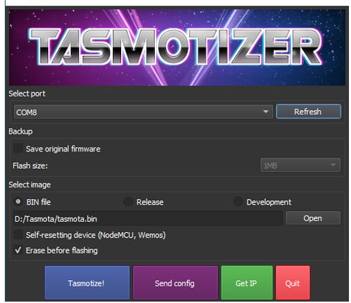
           After installation open run Tasmotizer .


Select the port where you are using the ESP 01 .  Select the " tosmta bin ". file and click on Tasmotze .


After flushing on esp01, connect esp 01 as the given diagram.


NOTE- ESP01 Can run with only 3,2 volt DC, So we are using here 3.2 voltage regulator IC here

Power up the Circuit.
Use the PC or mobile phone and search WiFi You will find a new wifi , First time when you open it it will re direct on the given page .Fill your WiFi user name and password then save it.
Click on Configuration
Click on configuration Module.

And select Generic 18 then save.

Select the DHT-11 on GPIO-0 and GIPO-2  for LED then save.


After while a moment screen will come on your PC. or Mobile with all Data .


You can control the LED on off and brightness from the screen 


For more clarification please visit on given links. 

https://youtu.be/vydq-e4-LSE


THANK  YOU


Comments